Instrument
Summary
The following table summarizes the specification of MIRIS.
Item |
Parameter |
Specification |
Remark |
|---|---|---|---|
Aperture |
80 mm |
||
F-number |
F/2 |
||
Focal length |
160 mm |
||
Field of View |
3.67°×3.67° |
||
Teledyne PICNIC (HgCdTe) |
|||
Detector array |
256 × 256 |
||
Pixel size |
40 μm |
||
Pixel scale |
51.6″ |
||
Broadband |
1.1 & 1.6 μm |
Δλ/λ ≳ 0.5 |
|
Narrowband |
|
||
Orbit |
Low Earth, Sun-synchronous orbit |
||
Altitude |
about 620 km |
||
Inclination |
97.8° |
||
MLTAN [1] |
22.3 o'clock |
||
Telescope
The telescope of MIRIS is a refractive system with small aperture of 80 mm, composed of 5 lenses. It provides wide field-of-view of 3.67°×3.67°. To evade the light from outside of about 40° from the field of view, the telescope equips Winston cone baffle. The barrel part of telescope is passively cooled down to and kept at the temperature of about 195 K. The following figure shows the schematic of the MIRIS telescope.
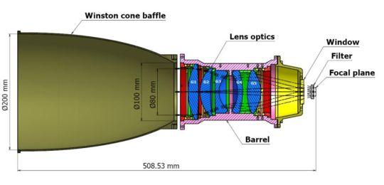
Schematic diagram of the MIRIS telescope.
Detector
For the infrared detector, MIRIS uses Teledyne PICNIC sensor of 256 × 256 array. The array is composed of 4 quadrants of 128 × 128 array. The pixel size is 40 μm and projected pixel scale is 51.6″. We cool down the detector to the temperature of 90 K with the microcooler, Ricor's K508.
The detector integrates the electron counts for n frames and resets it at the (n + 1)-th frame. Therefore, we need to take differentiate the integrated counts to get the physical intensity. n is adjustable, but our nominal value is 10. The detector readout interval is also adjustable, but we fix it to 2 seconds.
Filters
We have 6 filter positions on the filter wheel. Two positions are filled with
blocking filters which are used to block the light during MIRIS is not
observing and to measure the dark current. Though we call them BLANK1 and
BLANK2 filters, they are not real blank but blocking. Remaining 4
positions are filled with two broadband filters (1.1-μm and 1.6-μm bands;
hereafter, I and H bands, respectively), one narrowband filter (Paα
line filter; hereafter, PAAL) and one dual-pass filter (Paα continuum
filter; hereafter, PAAC). Though we internally call the two broadband
filters I and H bands, they are different from conventional ones and
has wider band width (Δλ/λ ≳ 0.5). These filters are optimized for the study
of near-infrared background and also adopted for the Wide Field Imagers of
CIBER (Cosmic Infrared Background Experiment). The following picture shows the
filter wheel integrated in the cold box. From the one at 11 o`clock position
in clockwise direction, the filters are BLANK1, I, H, PAAL,
PAAC, and BLANK2.
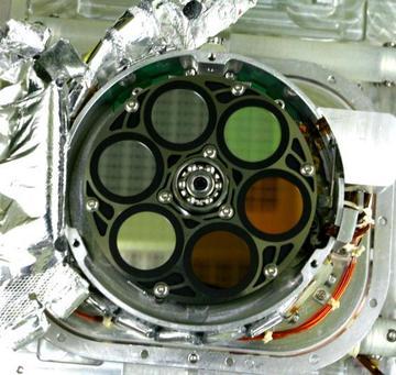
Picture of the filter wheel in the cold box.
The specification of filters are summarized in the following table:
Filter |
|
|
|
|
|---|---|---|---|---|
Nominal wavelength |
1.1 μm |
1.6 μm |
1.876 μm |
1.84 & 1.92 μm |
Band width (FWHM) |
0.550 μm |
0.910 μm |
24 nm |
25 & 25 nm |
The transmittance of filters are shown in the following figure:
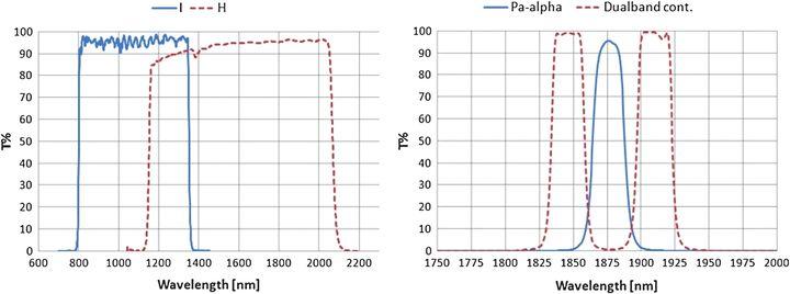
Transmittance curves of the MIRIS filters.